LGB Screw Vacuum Pump
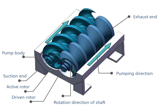
Screw vacuum pump working principle diagram
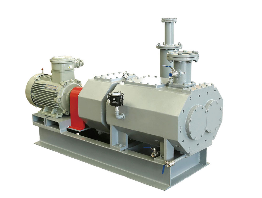
LGB type screw vacuum pump using range
LGB type screw vacuum pump, is the use of a pair of screw, made in the pump shell synchronous high-speed reverse rotation of the effects of the suction and exhaust and suction device, because the screw and has a certain gap between the screw, so the pump work, there is no friction between each other, smooth running, low noise, working cavity without lubricating oil, therefore, can dry screw pump pumping gas containing water vapor and a small amount of dust; Due to the limit of LGB type screw vacuum pump pressure can reach 5 pa, so type LGB screw vacuum pump can be widely used in chemical industry, metallurgy, electronics, petroleum, aerospace, tools, paper, packaging, food, medicine, medical apparatus and instruments, and information engineering, biological engineering, microelectronics and other fields.
LGB type screw vacuum pump performance characteristics
1. The working chamber without any medium, can clean vacuum;
2. Through the high precision dynamic balancing, high-speed operation, no friction between rotating parts, and long service life;
3. The gas inside the pump is compressed, appropriate extraction can non-condensable gas;
4. A single pump work scope is big, you can draw from the atmosphere to below 100 pa;
5. Working cavity and the rotor of the screw surface can be anti-corrosion treatment, so as to adapt to bad working condition;
6. Compared with mechanical vacuum pump oil seal type, condensable sexual material won't be stuck inside the pump, free of oil and gas and oil mist emissions, environmental preferred;
7. Compared with liquid ring pump, need only, the application of recycled cooling water is pumped gas does not contact with water, avoid the influence of water temperature of vacuum, materials easy to recycle, can save link of sewage disposal, and lower limit pressure, composition of screw vacuum unit roots for more efficient.
Model and main technical parameters
| Screw vacuum pump model | LGB-70 | LGB-100 | LGB-200 | LGB-300 | ||
| The extraction rate (50 hz) | Litres per second (L/s) | 70 | 100 | 200 | 300 | |
| M cubic/hour after (m³/h) | 250 | 360 | 720 | 1080 | ||
| Extreme pressure (50 hz) | Palmer (Pa) | ≤5 | ≤5 | ≤5 | ≤5 | |
| The maximum exhaust pressure | KPa (kPa) | 120 | 120 | 120 | 120 | |
| Motor power (50 hz) | Kilowatts (kW) | 7.5 | 15 | 18.5 | 37 | |
| speed | Revolutions per minute (RPM) | 2900 | 2880 | 2880 | 2880 | |
| The connection | Inlet diameter | Mm (mm) | 50 | 80 | 100 | 125 |
| Exhaust diameter | Mm (mm) | 45 | 65 | 65 | 80 | |
| lubricant | Before the end cover gear oil | L (L) | 1 | 1.3 | 2.8 | 4.2 |
| The cooling water | traffic | Litres/minute (L/min) | 30-35 | 30-35 | 30-35 | 30-35 |
| pressure | MPa (MPa) | 0.15-0.25 | 0.15-0.25 | 0.15-0.25 | 0.15-0.25 | |
| The water temperature | Degrees Celsius (℃) | ≤25 | ≤25 | ≤25 | ≤25 | |
| interface | G1/2″ | G1/2″ | G1/2″ | G1/2″ | ||
| The highest design temperature | Air intake | Degrees Celsius (℃) | ≤50 | ≤50 | ≤50 | ≤50 |
| exhaust | Degrees Celsius (℃) | 150 | 150 | 150 | 150 | |
| Lubricating oil | Degrees Celsius (℃) | 50 | 50 | 50 | 50 | |
| Seal type | The air inlet end | Oil seal | Oil seal | Oil seal | Oil seal | |
| Exhaust side | Mechanical seal + oil seal | Mechanical seal + oil seal | Mechanical seal + oil seal | Mechanical seal + oil seal | ||
| Shaft extension place | Mechanical seal | Mechanical seal | Mechanical seal | Mechanical seal | ||
| Room temperature operating range | Degrees Celsius (℃) | 5-40 | 5-40 | 5-40 | 5-40 | |
| The noise | Decibels (dB) | ≤80 | ≤80 | ≤80 | ≤80 | |
| Weight (not including silencer) | Dry grams (kg) | 500 | 665 | 1020 | 1300 | |
| Shape (single pump) | Length X width X height | Mm (mm) | 1360X500X695 | 1650x475X680 | 1740x570x740 | 2100x800x790 |
| Appearance (including muffler, inlet ball valve) | Length X width X height | Mm (mm) | 1360X960X700 | 1650x847X933 | 1740x960x980 | 2100×1100X1030 |
Note: the technical parameters listed in the table are obtained from measurement, the following provisions conditions
Atmospheric pressure 1.01 X10⁵Pa/cooling water temperature 15 ℃ / humidity of the air inhaled air temperature 20 ℃ / 70% extraction rate deviation plus or minus 10% of pump type LGB - A meaning; LGB A screw straight league vacuum pump (L said screw, G dry vacuum pump, varying pitch) B A L/S extraction rate
Structure diagram
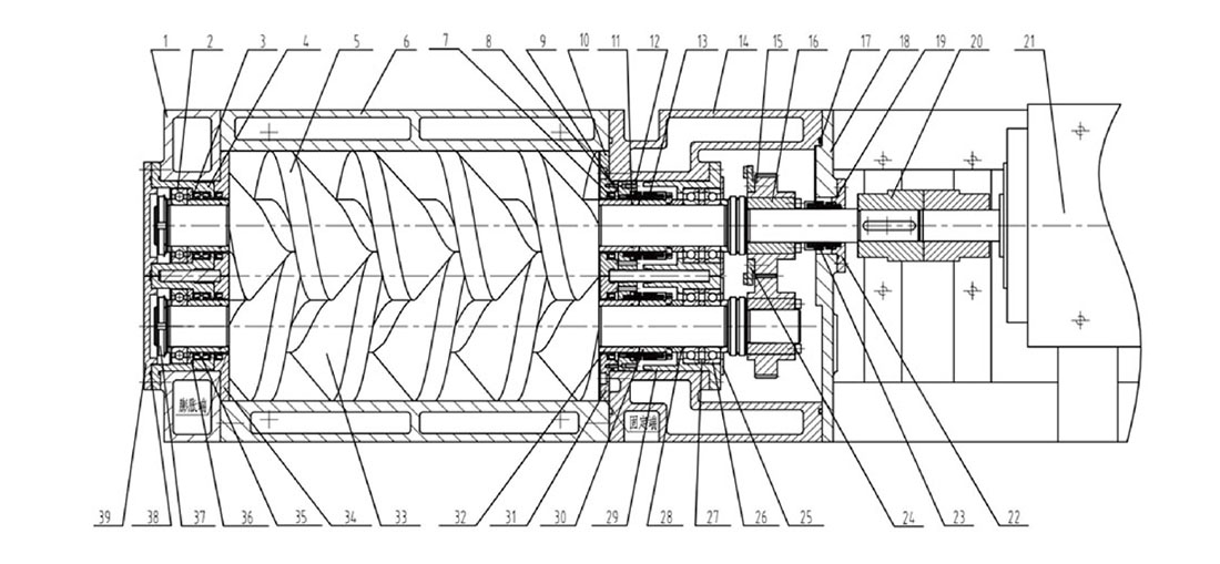
| 1. After the end cover | 2. Deep groove ball bearings | 3. The oil seal | 4. After the bearing seat | |
| 5. The active rotor | 6. The pump body | 7. The skeleton oil seal | 8. Sealing Ring | |
| 9. Sealing Ring 2 | 10. Before The Active Positioning Plate | 11. Seal FIG. 3 | 12. The Static Ring | |
| 13. A Mechanical Seal | 14. The Front End Cover | 15. The Gear | 16. Locking | |
| 17. Sealing Ring Four | 18. The Front Cover | 19. Sealing Ring Five | 20. Coupling | |
| 21. The Motor | 22. The Machine Seal Gland | 23. The Mechanical Seal | 24. The Oil Pan | |
| 25. The Front Bearing Cover | 26. The angular contact ball bearings | 27. The bearing inner and outer ring | 28. Bearing washer | |
| 29. The front bearing | 30. 30. Machine shaft sleeve | 31. The former passive positioning plate | 32. Oil seal shaft sleeve | |
| 33. Driven rotor | 34. After positioning plate | 35. The seal ring | 36. After bearing inner ring | |
| 37. Round nut | 38. The sealing ring of six | 39. After the bearing cover | ||


